AVR マイコン + シフトレジスタで7セグメントLEDを制御したい
知識材料
- [ATTiny85]
- [SN74HC595]
利用環境
- [Arduino IDE 1.8.7]
今回のゴール
7セグメントLEDを制御する回路と、プログラムを作成する。 作成した回路は外部からのデータ入力で、LEDの表示を変えることができるようにする
実践
回路作成

Arduino 側ソースコード
#define UART_Tx 3
#define UART_Rx 1
#include <avr/io.h>

#include <SoftwareSerial.h>
#include <stdlib.h>
SoftwareSerial mySerial(UART_Rx, UART_Tx); // RX, TX

int SEG_7[] = {0x7E, 0x12, 0xBC, 0xB6, 0xD2,
              0xE6, 0xEE, 0x32, 0xFE, 0xF2, 0x00};
//   H2
// H4  H1
//   H8
// L8  L2
//   L4    L1      H8421 L8421

void Show7Seg(int val)
{
    Show7Seg2(val, true);
}
void Show7Seg2(int val, bool zeroSup)
{
  for(int i = 1; i <= 4; i++ )
  {
    int writeVal = val % 10;
    val /= 10;

    if( zeroSup && (val == 0 && writeVal == 0 ) && i != 1)
      writeVal = 10;

    __Show7SegWithDigit( writeVal , i);
  }
}
void __Show7SegWithDigit(int val, int dig)
{
//  Reset();
//  Send_Byte(0xFF, false); // 非表示
//  Send_Byte(0x00);        // 数字なし

  switch(dig)
  {
    case 1:
      Send_Byte(0xFE, false);
      break;
    case 2:
      Send_Byte(0xFD, false);
      break;
    case 3:
      Send_Byte(0xFB, false);
      break;
    case 4:
      Send_Byte(0xF7, false);
      break;
    default:
      Send_Byte(0xF0, false);
      break;
  }

  Send_Byte(SEG_7[val]);
  delayMicroseconds(100);
}

///
/// Shift Register
int PIN_SER = 0;
int PIN_SRCLK = 4;
int PIN_RCLK = 2;

void Shift()
{
  digitalWrite(PIN_SRCLK, HIGH);
  delayMicroseconds(1);
//    delay(1);
  digitalWrite(PIN_SRCLK, LOW);
}
void Regist()
{
  digitalWrite(PIN_RCLK, HIGH);
  delayMicroseconds(1);
//  delay(1);
  digitalWrite(PIN_RCLK, LOW);
}
void Reset()
{
  /*
  digitalWrite(PIN_SER, LOW);
  digitalWrite(PIN_SRCLK, LOW);
  digitalWrite(PIN_RCLK, LOW);
  */
  PORTB &= ~(_BV(PIN_SER) | _BV(PIN_SRCLK) | _BV(PIN_RCLK));
}
void Send_Byte(int bits)
{
  Send_Byte(bits, true);
}

void Send_Byte(int bits, bool autoRegist)
{
  for( int i = 0; i < 8; i++ )
  {
    if( (( 1 << i) & bits) == 0 )
    {
//      digitalWrite(PIN_SER, LOW);
      PORTB &= ~_BV(PIN_SER);
    }
    else
    {
//      digitalWrite(PIN_SER, HIGH);
      PORTB |= _BV(PIN_SER);
    }

    Shift();
  }
  if( autoRegist )
    Regist();
}

///
/// timer
unsigned long interval = 100;
unsigned long prevMill = 0;
bool onTime()
{
  bool ret = false;
  unsigned long currentMill = millis();
  if( currentMill - prevMill >= interval )
  {
    prevMill = currentMill;
    ret = true;
  }
  return ret;
}


int numnum = 8888;
/*
bool b_rxRead = false;
void onSerial()
{
//  char c = RxByte();
//  TxByte(c);

//  detachInterrupt(0);
//  numnum = 0;
  b_rxRead = true;
}
*/

void setup() {
  // put your setup code here, to run once:
  pinMode(PIN_SER, OUTPUT);
  pinMode(PIN_SRCLK, OUTPUT);
  pinMode(PIN_RCLK, OUTPUT);

//  attachInterrupt(0, onSerial, RISING);
//  b_rxRead = true;
  mySerial.begin(38400);

  Reset();
  outputTest();
}

char serialBuf[16];
int  serialCount = 0;

///
/// Main Loop
void loop() {
  // put your main code here, to run repeatedly:
  //if(mySerial.available())
  {
    char t = mySerial.read();
    if( t != -1 )
    {
      if ( t == 0x0d ||
           t == 0x0a ||
           serialCount == 14)
      {
        if( serialCount != 0 )
        {
          serialBuf[serialCount] = 0x00;
          int num = atoi(serialBuf);
          serialCount = 0;
          numnum = num;
        }
      } else {
        serialBuf[serialCount++] = t;
      }
    }
  }

  Show7Seg(numnum);
}
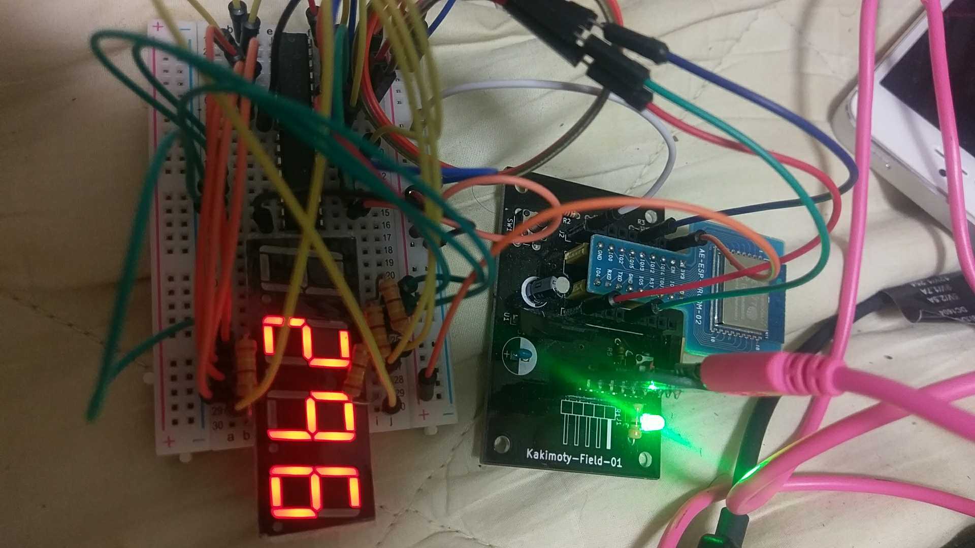
実行と結果
まとめ
ダイナミック表示がチラつくことがあるので、改修が必要かと思われます。
シリアルからのデータ受信が、数値ではないなど不正だった場合のようなエラー処理が未熟なので、そのへんももう少し考えたい